NIC Teaming to Cisco Nexus vPC
Introduction
High availability at the server access layer is a common enterprise requirement. This lab demonstrates how Cisco Nexus vPC and Windows Server NIC Teaming using LACP can provide active-active connectivity while eliminating single points of failure.
Technology Overview
Link Aggregation Control Protocol (LACP) in Windows Server
Windows Server supports IEEE 802.3ad Link Aggregation Control Protocol (LACP) through the built-in NIC Teaming feature, allowing multiple physical network adapters to operate as a single logical interface. During operation, the server exchanges Link Aggregation Control Protocol Data Units (LACPDUs) with connected switches to dynamically establish the team, verify member links, and detect failures. Unlike static link aggregation, LACP automatically validates configuration consistency and removes failed links from the bundle, improving both availability and operational reliability.
Cisco Nexus Virtual Port Channel (vPC) Concepts
Cisco Nexus Virtual Port Channel (vPC) enables two independent Nexus switches to present themselves as a single logical LACP endpoint to downstream devices. This allows a server to establish one port-channel across both switches while each Nexus maintains its own independent control plane. Both links remain active simultaneously, providing active-active forwarding, increased bandwidth utilization, and chassis-level redundancy without requiring traditional switch stacking.
The technology relies on two dedicated mechanisms. The vPC Peer-Link synchronizes forwarding state between the switches, including MAC address tables, IGMP snooping information, and LACP state, while the Peer-Keepalive link independently monitors peer availability to detect failures and prevent split-brain conditions.
Architecturally, vPC is Cisco’s implementation of Multi-Chassis Link Aggregation (M-LAG). Similar technologies include Huawei M-LAG and Alcatel-Lucent Enterprise MC-LAG, all of which allow a downstream device to form a single logical link aggregation group across two independent switches while maintaining active-active forwarding and chassis redundancy.
Topology & Prerequisites
Network Diagram & EVE-NG Setup
In this lab environment, EVE-NG is deployed as a virtual machine hosted on a VMware ESXi hypervisor. All configuration tasks, verification procedures, and failover validation exercises presented throughout this article are performed using the topology illustrated below.
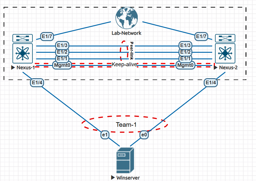
This lab uses a dedicated Mgmt0 interface for the out-of-band vPC Peer-Keepalive, while a three-member LACP port channel (Eth1/1–Eth1/3) forms the vPC Peer-Link between both Nexus switches. The Windows Server connects through Eth1/4 on each switch, creating a single active-active LACP NIC team (Team-1) using its e0 and e1 interfaces.
Hardware & Software Requirements
Images:
EVE-NG can be deployed on several supported virtualization platforms, including VMware ESXi, VMware Workstation and VirtualBox. Refer to the official documentation for installation instructions.
Phase 1: Base Nexus Switch Configuration
Enabling Management & Core Features (lacp, vpc)
The complete configurations for both Nexus switches are available in the GitHub repository.
This lab used a minimal, single-default-VLAN configuration to keep the focus entirely on the core behaviors of vPC and NIC Teaming.
NX-OS utilizes a modular architecture where most protocol engines are disabled by default to optimize CPU and memory allocation. To build this topology, you must explicitly enable feature lacp to process Link Aggregation Control Protocol frames, and feature vpc to instantiate the multi-chassis synchronization control plane.
These features must be enabled on both Nexus-1 and Nexus-2.
1
2
3
configure terminal
feature lacp
feature vpc
Configuring the vPC Peer-Keepalive (PKAL) Link
The vPC Peer-Keepalive (PKAL) link is a dedicated out-of-band Layer 3 control path used exclusively for peer liveness detection and split-brain prevention. It exchanges periodic heartbeat messages over UDP port 3200, allowing each Nexus switch to verify the availability of its peer independently of the vPC Peer-Link.
The following IP addressing scheme is assigned to the Mgmt0 interfaces and will be used for the vPC Peer-Keepalive connection:
Nexus-1:
1
2
3
interface mgmt0
ip address 192.168.100.1/24
no shutdown
Nexus-2:
1
2
3
interface mgmt0
ip address 192.168.100.2/24
no shutdown
Defining the vPC Domain
A vPC domain is a logical administrative grouping that pairs two distinct physical Nexus switches into a single virtualized chassis layer sharing a unique Domain ID.
The vPC role determines the operational responsibility of each Nexus peer, where the switch with the lower vPC role priority value is elected as the Primary, while the other becomes the Secondary peer. The Primary vPC peer provides role coordination, performs consistency decision handling, and maintains synchronization with the Secondary through the vPC peer-link.
Nexus-1:
1
2
3
4
5
6
7
8
9
10
11
12
13
14
15
16
17
18
19
20
21
! Create the vPC domain. The domain ID must match on both Nexus peers.
!
vpc domain 1
!
! Configure the vPC Peer-Keepalive over the dedicated management network using the management VRF.
!
peer-keepalive destination 192.168.100.2 source 192.168.100.1 vrf management
!
! Set Nexus-1 as secondary peer (Nexus-2 priority will be set to 100 and become primary)
!
role priority 200
!
!
! Allow either vPC peer to forward traffic destined for the virtual gateway MAC, improving forwarding efficiency.
!
peer-gateway
!
!Automatically restores vPC member ports after a complete dual-switch outage if the peer remains unavailable.
!
auto-recovery
!
Nexus-2:
1
2
3
4
5
vpc domain 1
peer-keepalive destination 192.168.100.1 source 192.168.100.2 vrf management
role priority 100
peer-gateway
auto-recovery
Configuring the vPC Peer-Link
The vPC Peer-Link is a high-bandwidth Layer 2 trunk port channel that serves as the primary synchronization path between the two vPC peers. It synchronizes critical control-plane state, including MAC address tables and IGMP snooping information, while also forwarding specific data-plane traffic, such as traffic destined for orphan ports or during certain failure scenarios.
Configuration Note: The interface bundling and peer-link configurations must be identical on both Nexus-1 and Nexus-2. The configuration below creates the underlying LACP port-channel across interfaces
Eth1/1toEth1/3and binds it as the vPC peer-link backbone.
Peer-Link Configuration:
1
2
3
4
5
6
7
8
9
10
11
12
13
14
15
16
17
18
19
20
21
22
23
24
25
26
27
28
interface port-channel1
  description vPC Peer-Link
  switchport
  switchport mode trunk
  spanning-tree port type network
  vpc peer-link
  no shutdown

interface ethernet1/1
  description vPC Peer-Link
  switchport
  switchport mode trunk
  channel-group 1 mode active
  no shutdown

interface ethernet1/2
  description vPC Peer-Link
  switchport
  switchport mode trunk
  channel-group 1 mode active
  no shutdown

interface ethernet1/3
  description vPC Peer-Link
  switchport
  switchport mode trunk
  channel-group 1 mode active
  no shutdown
Verifying Peer-Link and Keepalive Status
Once the configuration is applied to both switches, you must execute validation commands to confirm that the peer-keepalive heartbeat is active and the peer-link has successfully initialized the vPC control plane.
vPC Verification Commands:
1
2
3
show vpc
show vpc role
show port-channel summary
Phase 2: Downstream vPC Configuration
Creating the Host-Facing vPC Port-Channel
With the backbone established, you must now build the logical multi-chassis port-channel interfaces that terminate downstream directly on the Windows Server.
Nexus-1:
1
2
3
4
5
6
7
8
9
10
11
12
interface port-channel10
 description ### Lab_Winserver_Portchannel ###
 switchport
 switchport mode access
 vpc 10
 no shutdown

interface ethernet1/4
  description ### Nexus_1_winserver_link ###
  switchport
  channel-group 10 mode active
  no shutdown
Nexus-2:
1
2
3
4
5
6
7
8
9
10
11
12
interface port-channel10
 description ### Lab_Winserver_Portchannel ###
 switchport
 switchport mode access
 vpc 10
 no shutdown

interface ethernet1/4
  description ### Nexus_2_winserver_link ###
  switchport
  channel-group 10 mode active
  no shutdown
At this stage the host-facing member interface
Eth1/4is currently suspended (in both nexus switches) because it has not yet received LACP PDUs from the downstream Windows Server. Consequently, the logical host port-channelPo10remains down, though it has successfully passed all vPC configuration consistency checks and is completely ready to forward traffic once the server-side NIC teaming active negotiation begins.
Nexus-1 Showing eth1/4 down state:
1
2
3
4
5
6
7
8
9
10
11
12
13
14
15
16
17

vPC status
----------------------------------------------------------------------------
Id    Port          Status Consistency Reason                Active vlans
--    ------------  ------ ----------- ------                ---------------
10    Po10          down*  success     success               -

Ethernet        VLAN    Type Mode   Status  Reason                 Speed     Port
Interface                                                                    Ch
#
--------------------------------------------------------------------------------
Eth1/1          1       eth  trunk  up      none                     1000(D) 1
Eth1/2          1       eth  trunk  up      none                     1000(D) 1
Eth1/3          1       eth  trunk  up      none                     1000(D) 1
Eth1/4          1       eth  access down    suspended(no LACP PDUs)  auto(D) 10
Phase 3: Windows Server NIC Teaming Configuration
Accessing Server Manager
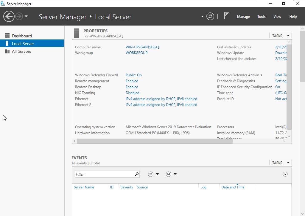
Open Server Manager, then navigate to Local Server to access the NIC Teaming configuration.
Configuring NIC Teaming Settings
Click the underlined Enabled link next to NIC Teaming in Server Manager to open the NIC Teaming management window.
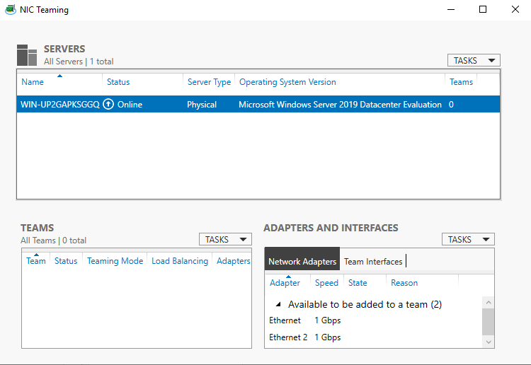
The Adapters and Interfaces section lists all available physical network adapters, which in this lab are Ethernet and Ethernet 2. The remaining sections display any existing NIC teams and their associated network interfaces.
From the TASKS menu, select New Team… to create a new NIC team.
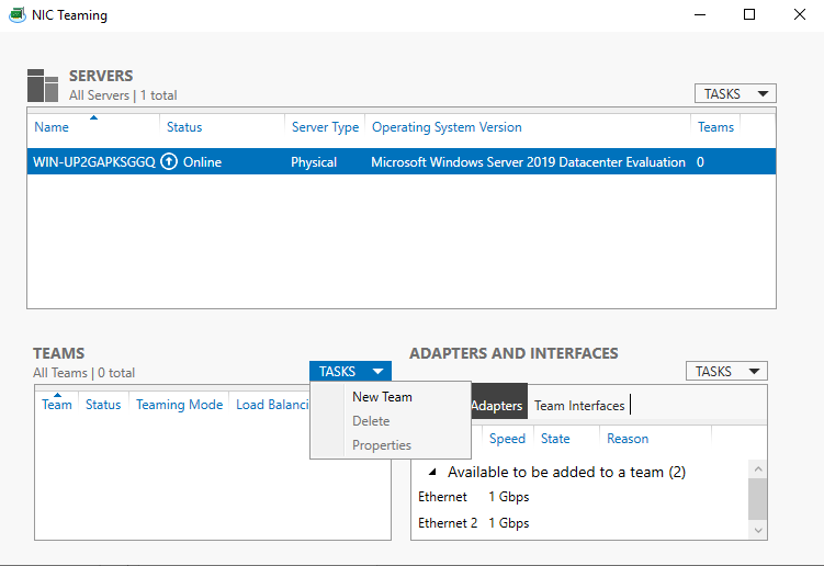
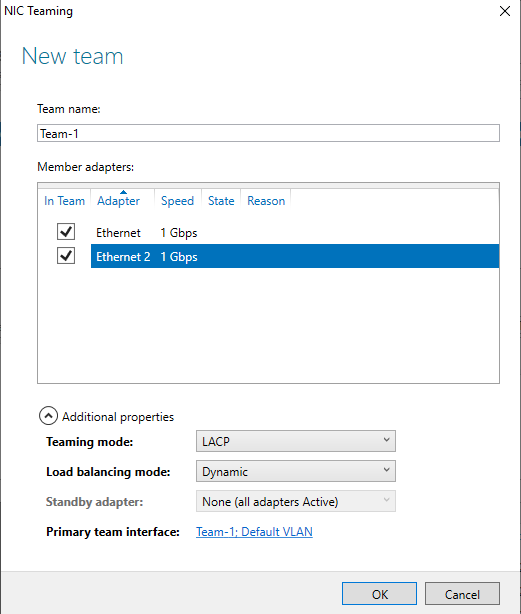
Create a new NIC team named Team-1, add both Ethernet and Ethernet 2 as member adapters, then configure the teaming mode as LACP with Dynamic load balancing, as shown below.
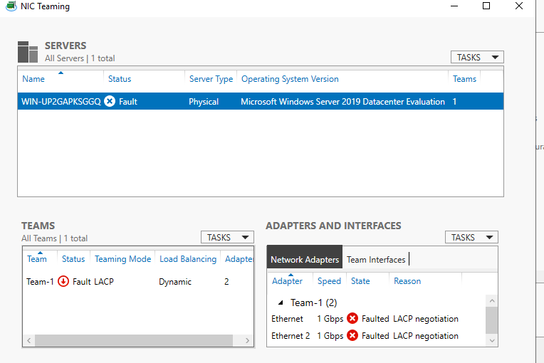
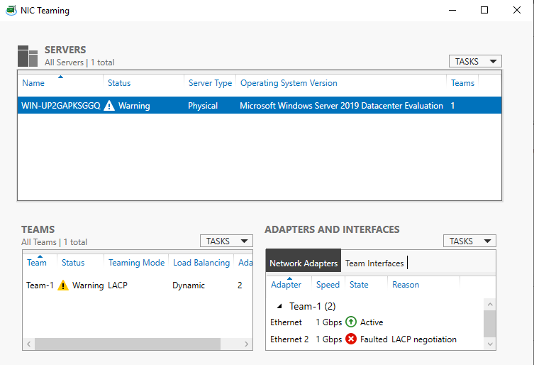
The NIC team initially entered a Fault state because LACP negotiation had not yet reached a synchronized state between the Windows Server and the Nexus vPC port-channel.
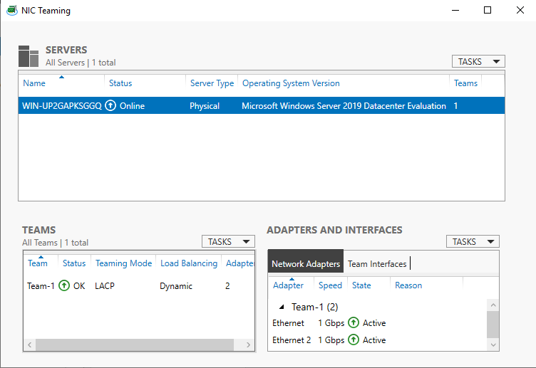
After exchanging LACP negotiation packets with the Nexus vPC port-channel, the Windows NIC Teaming service successfully synchronized both member adapters. The team transitioned from Fault to an active state once the LACP session became established.
Verification & Validation
Nexus Side Verification
The following verification output confirms that the vPC peer-link and vPC member port-channels are successfully established and operating normally. The peer-link Po1 is up, and the vPC port-channel (Po10) shows up status with successful consistency checks, indicating proper synchronization between both Nexus peers.
Nexus-1:
1
2
3
4
5
6
7
8
9
10
11
12
13
14
15
16
17
18
19
vPC Peer-link status
---------------------------------------------------------------------
id    Port   Status Active vlans
--    ----   ------ -------------------------------------------------
1     Po1    up     1


vPC status
----------------------------------------------------------------------------
Id    Port          Status Consistency Reason                Active vlans
--    ------------  ------ ----------- ------                ---------------
10    Po10          up     success     success               1

--------------------------------------------------------------------------------
Group Port-       Type     Protocol  Member Ports
      Channel
--------------------------------------------------------------------------------
1     Po1(SU)     Eth      LACP      Eth1/1(P)    Eth1/2(P)    Eth1/3(P)
10    Po10(SU)    Eth      LACP      Eth1/4(P)
Windows Side Verification
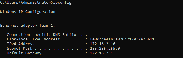
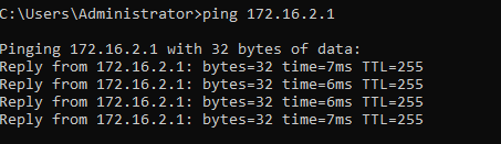
Windows verification confirms successful NIC Team operation, with ipconfig showing a valid DHCP-assigned IP address from the lab network.
Gateway reachability is confirmed through successful ping tests.
Failure Scenario & Redundancy Testing
Scenario A: Simulating a Single Link Failure (Host to NXOS-1)
To simulate a single link failure, shut down interface Ethernet 1/4 on Nexus-1 and observe the traffic failover behavior.
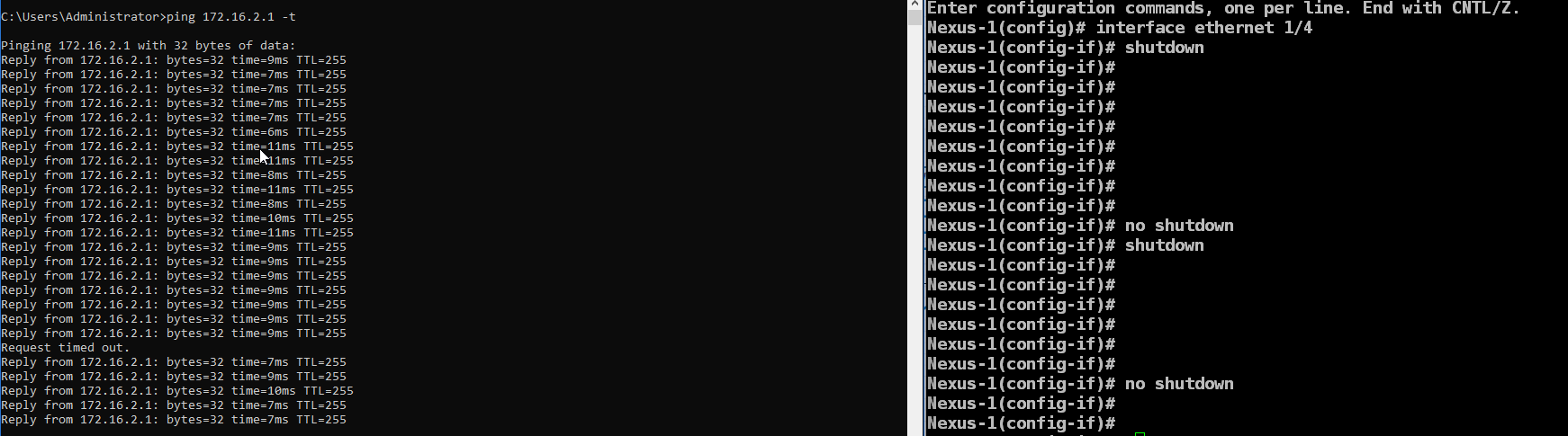
Shutting down the interface causes no packet loss, but bringing it back up (no shutdown) triggers a brief drop. This happens during the LACP convergence window, where traffic is hashed over the restored link before hardware forwarding tables fully synchronize.
Scenario B: Simulating a Switch Failure (Powering off NXOS-1)
To simulate a complete node failure, power off Nexus-1 to observe how the remaining vPC peer handles the workload.
Powering off the active switch causes a brief drop as the host’s NIC team registers the dead link and the remaining vPC peer updates its forwarding tables.
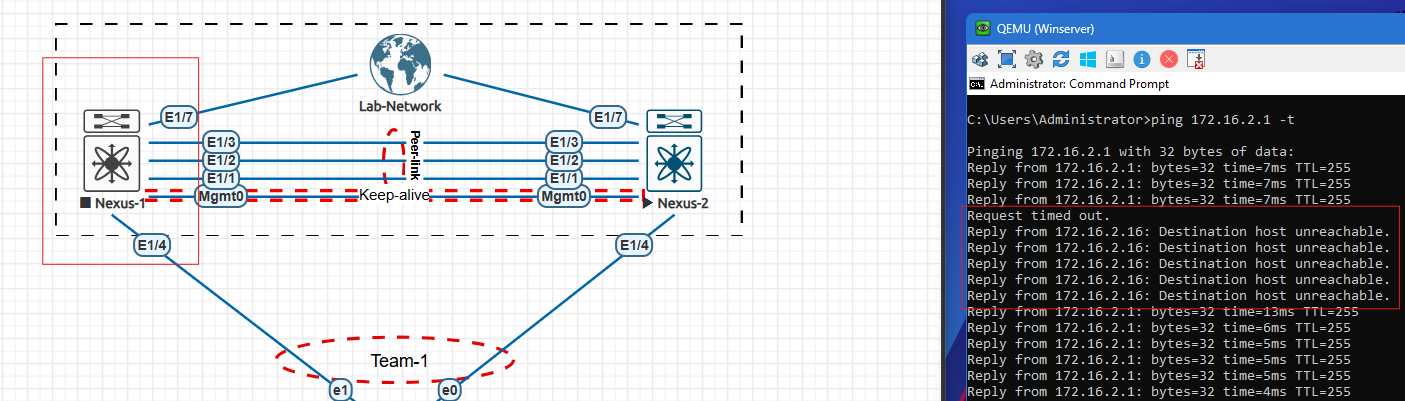
Traffic quickly recovers and stabilizes over the single active link once the Windows Server NIC team marks the failed interface as faulted.
Scenario C: vPC Peer-Link Failure (Dual-Active/Split-Brain Prevention)
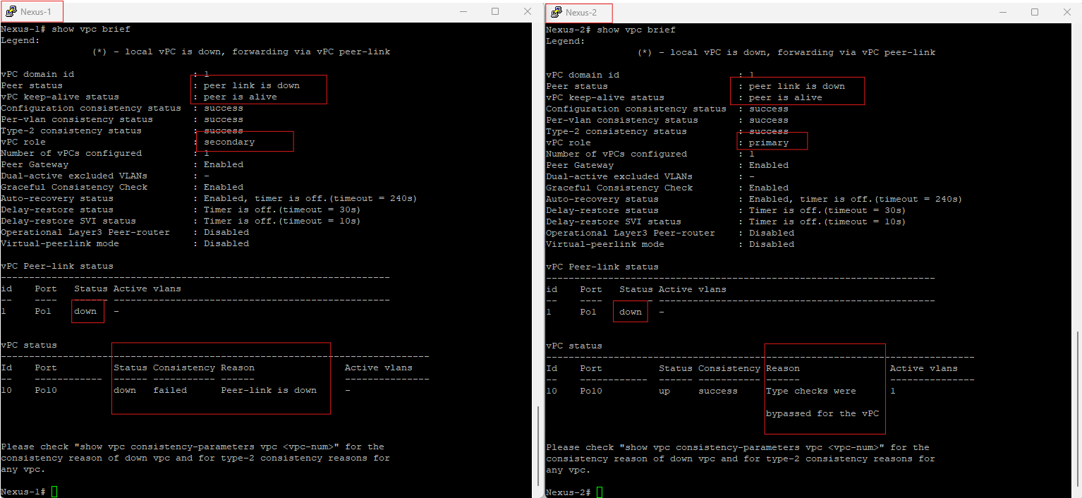
When the primary vPC Peer-Link ruptures while the Peer-Keepalive remains up, the vPC domain invokes an active loop-prevention sequence. The operational secondary peer (Nexus-1 in this case) instantly disables its local host-facing vPC member ports and any vPC VLAN SVIs to isolate itself from the data plane. The vPC primary peer (Nexus-2 in this case) continues to forward all upstream and downstream traffic, maintaining deterministic traffic symmetry and preventing corrupted MAC address table sync across the network topology.
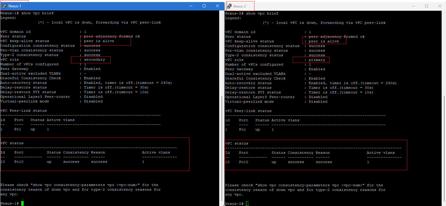
Verify the baseline environment using show vpc brief. Both switches should display a healthy peer adjacency, an operational peer-link Po1, and active vPC member ports Po10 split across the primary and secondary nodes.
To simulate a pure peer-link failure, shut down Port-Channel 1 on Nexus-1. This breaks the primary data and control path between the switches while leaving the separate peer keep-alive link intact.

Because the keep-alive link confirms both switches are still running, dual-active prevention triggers. The secondary switch (Nexus-1) immediately suspends its vPC member ports to prevent a split-brain condition, while the primary switch (Nexus-2) keeps its ports up to handle all traffic.
Conclusion
This lab demonstrated that integrating Windows Server NIC Teaming with Cisco Nexus vPC provides a resilient LACP-based high-availability solution. By testing link, switch, and peer-link failure scenarios, the design successfully maintained connectivity through automatic failover, synchronization, and split-brain prevention mechanisms. This architecture eliminates single points of failure at the server access layer and ensures continuous connectivity for critical infrastructure workloads.
Although this lab uses a simplified topology, the same design principles are widely applied in production data centers to provide resilient server connectivity without relying on traditional switch stacking.